Control
| Tags | Control |
|---|
Basic physics
If you have a potential field, then you can create a conservative force by taking the negative gradient.
What is control?
Control is this: we have a target point and a current state. How do we get to this target?
We start with an equation of motion, like . This tells us how the system will respond, period.
Often, this equation of motion is not very interesting. What you really want might be to move this particle to a certain target. For this, you introduce a perturbance force, i.e. you derive some expression for .
Now, after you derive the expression for , you might get something like . This gives us a new equation of motion. You can understand this as adding something to the existing system and changing its behavior. Commonly, depends on the distance from the goal and some speed component (viscous friction). We call this final formulation a closed-loop equation of motion.
Unactuated Systems
We want to work towards control, which involves putting an actuating force on the joints. But before we do that, let’s explore how unactuated systems behave. In these systems, we aren’t concerned with the force we apply .
The Spring and Damper system
It’s common to assume that we essentially set the target point and attach springs to the points (joints) and see what happens when we run time forward. We can imagine this as a simple mechanical system

The springs are often “damped” by some natural friction term.
Conservative systems
We can employ the Lagrange equation again. If we are not expecting to add any energy into the system

This gets us

And we know that with a derivative . The kinetic energy is . The derivative is , and taking the time derivative again gets you . This gets yo uthe following equation of motion.
This gets you the following equation of motion:
This is actually a differential equation with a natural frequency . Meaning, the larger the mass, the slower the swing. The stiffer the spring, the faster the swing. We can model the path as
Dissipative systems
All you need to do is to add an external force into the Lagrange equation, which is the friction force.

If we care about viscous friction, i.e. fluid-based friction, it depends on velocity: . The force is negative because we must apply an opposing force. If we rearrange, we get the equation of motion.
which we can rewrite as
The damping comes from the velocity component, or . The oscillation frequency comes from . We can create a new parameter (natural damping ratio) such that
Under this setup, we can rewrite the equation as the following:
If you solve the differential equation, you’ll get the time response as
which gives you an interesting insight: if , then the oscillation drops away. This is known as critical damping, and it depends on the parameters . At lower , we get under-damping, and at higher , we get overdamping (note that the time response changes; it’s no longer that function above)
More specifically, there are two things that you can change with these parameters
- Oscillation frequency: with larger or smaller , the system tends to oscillate faster
- The true damping frequency is
- Damping level: if you tune the correctly, you can hit the sweet spot at any value of . Specifically, if , we get critical dampening

Robot Linear Control
Now, we are finally ready to talk about robot control. We have some setup

where we have a target, and we want to find the force to drive the current joint. We make it a simple prismatic for now. Let’s start with a simple, frictionless environment .
Now, we want to derive some controlling force that gets this actuator to the target while respecting the equation of motion.
Potential function
One way of deriving this controlling force is to start with a potential function.
Because is a potential, the gradient is a conservative force. This is the force that is applied to the system. We know that the system follows an equation of motion, so we plug it in.

This gives us the control objective. A control objective gives the force given the current state of the system. In this case, we have
Asymptotic stability
What does it mean for a system to be stable? Well, one thing we could consider is asymptotic stability, meaning that we approach a steady state as . As it stands, the previously described system is not stable; it oscillates.
Generally, the condition for asymptotic stability is
We can easily satisfy this requirement by creating a dissipative force that is directly related to velocity, i.e. viscous friction.
which means that this dissipative force typically depends on , like . This allows us to formulate the following control objective
which gives us the Proportional-Derivative Control (PD)
PD Control
With the control being , we plug this into the equation of motion to get
Now, if we massage the equation and let and , then we get the following differential equation
This is an equation we described in the dissipative systems section above, and we know how it responds. As before, if , we get critical damping. Otherwise, we get overshooting / oscillation, or too slow.
The unit mass construction
We can just reverse the definitions of and solve for . If we do this, we get and . Critically, notice that the controller gains are linear in the mass. Therefore, it’s possible to create a controller that assumes linear mass. Then, we have once we know that mass of the system.
In other words, it’s possible to create an effective controller and scale it to any mass we need. If we don’t know the mass, we can estimate it. Here are some ways that you could get the gains
- Know the system parameters, and compute the gains to get perfect damping
- Guess the system parameters, compute the gains to get damping
- Just guess the gains. In this case, know that the gains affect the oscillation frequency, etc.
Nonlinear control

Let’s say that we have the robot joint again, but this time, there’s some friction term such that the equation motion is

How do we deal with this? Well, we could take the unit-mass controller and modify it to have
where and . We don’t necessarily assume we have access to the mass and friction, but we can have estimates. We’ll talk more about how we get these estimates later. If we estimate these components correctly, then the behavior of this nonlinear system will be identical to the behavior of the control under unit mass.
Also, note that this is constantly changing, so we need to edit our approximation. This gets us a control flowchart that looks like this

Moving towards motion control
We are getting closer to what we want in our control system: true motion control. What does this mean? Well, we want some system that allows us to input a desired trajectory, velocity, and accelerations and get a controller that operates on the joints.
Previously, the unit mass controller had a target position. We can also add a target velocity and a target acceleration. This yields

and the closed-loop system

If we let , then this is a second order system

that we know how to solve if we substitute the variables correctly. This gets us the following control loop
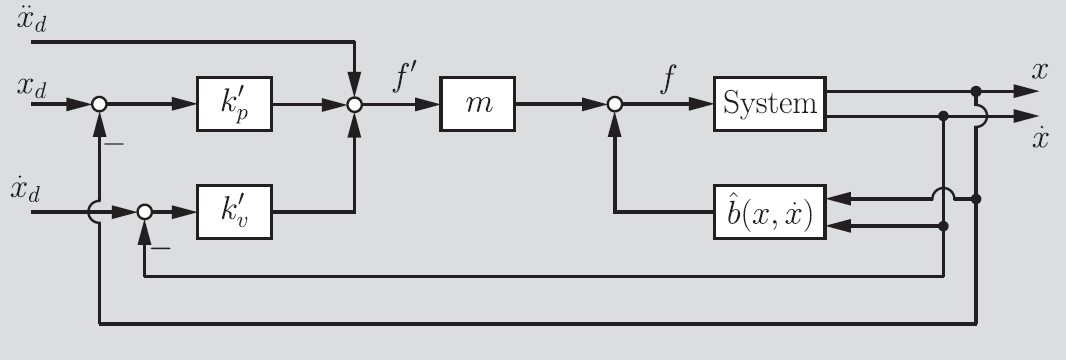
Disturbance rejection
The estimates of and can be inaccurate, which can create disturbances in the system that reduce stability. We can minimize these disturbances if we are smart about picking our gains. The larger the gain, the better we are at rejecting disturbances, because we are just operating in brute force mode.
Modeling the disturbance
Let’s assume that we can model this disturbance with some force , which we can assume (potentially quite erroneously) that it is constant. This gets us the following equation of motion

and the following diagram
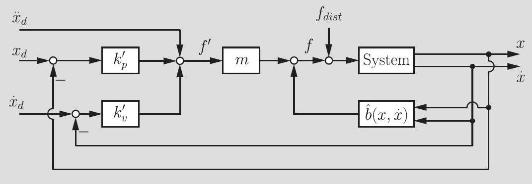
If we use the control structure as before, we actually see something pretty neat. Adding a constant force doesn’t change much; it just gets us a residual component in the closed loop behavior

Steady state error
If the closed loop system is at rest, then the equation becomes
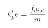
which tells us that the steady state error of this stationary system is

What does this mean? Well, it tells us that the joint / manipulator will come to rest at a place that isn’t the target. This is because the controller isn’t prepared to handle this disturbance force, and so the equilibrium is achieved in an incorrect spot.
These results also tell us that higher ’s lead to smaller errors, as previously discussed. Now, we can’t make the gains too large, because it increases the closed loop frequency and the robot may start to chatter. So, how do we resolve this problem?
Integral control
We could make the gains higher, or we could add another element in the control equation, the “I” in the PID controller. This gets the controller

and the closed-loop behavior

If we take the derivative again, we get

which shows that the steady-state error equation has , as desired.
PD for multi-link systems
Now, assuming that we had an IK solution and we are controlling in joint space, you can imagine little springs attached to each of the joints. This is in joint space control.
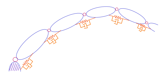
Now, you could just run a PD controller for each individual joint. And this works if we are moving sufficiently slow enough and don’t care too much about the intermediate points of the robot. This is because, given a sufficiently tuned controller, we will eventually reach the target position. However, as we saw previously in the equations of motion of a robot arm, joints can be coupled together, and they can also experience coriolis forces and centripital forces, etc. Therefore, no actuator is an island.
Or, more specifically, the PD controller at each joint would have a disturbance force as the following
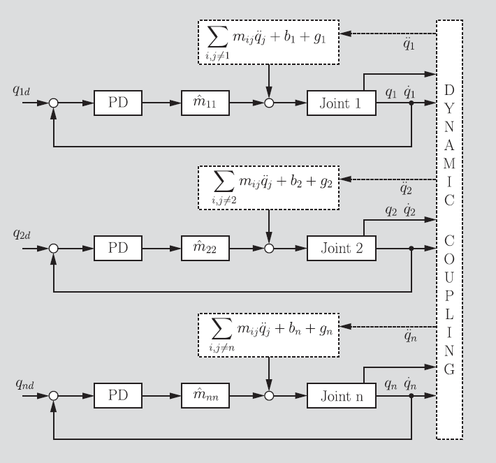
Analysis on individual PD control
Let’s say that we didn’t accommodate these forces for now, or rather, we assume a robust enough controller with high gains and an integral control. What can we say?
Well, we start off with the torque equation

which is asymptotically stable because the forces are either conservative or dissipative.
Now, let’s show that this is truly stable. If we plug in the torque to the robot equation of motion (and use the fact that is a gradient of a potential field, we get

If we rearrange, we get

In essence, this additional control term is just another potential energy term. The . So we can imagine that this is just a robot coming to rest in a viscuous fluid.
Dynamic PD control (Nonlinear Dynamic Decoupling)
Decoupling is when you want to bring back the old equation of motion . In reality, we have this equation

Now, if you know , you can just subtract them from the controller to do the decoupling. That is what this looks like:
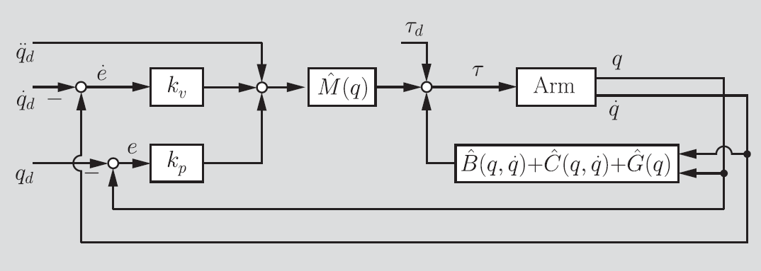
We implement this by using a torque controller on a unit mass (no coupling) and compensate

as long as we have an estimate of the different components. If you do this correctly, you’ll be able to send targets to all of the joints and prevent the other joints from unnecessary movement.
Operational Space Control
In task-oriented control (operational space control), you imagine a single spring added to the end of the robot
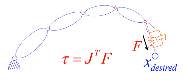
This gets you a potential field and an associated force at the end of the end-effector


Note that the force is negated because we are talking about the robot applying the force. We can use the jacobian to compute all the torques . This is much simpler than joint space control because we don’t have to worry about all the weird situations with joint coupling.
We can add an additional damping force by computing . The asymptotic stability condition is . If we put everything into joint space by using , we get

The is a positive definite matrix, so the quadratic form is positive. Therefore, as long as , the system is asymptotically stable.
Dynamics & Equations of Motion
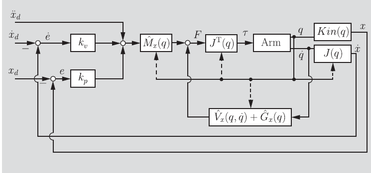
We can write out the equations of motion in operational space as follows:

Now, how are these quantities related to the joint space quantities? Well, we can use the fact that and that , but these quantities are equal. We also know that . Putting all of this together, we get that

In summary, these relationships are
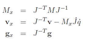
So if you know the mass matrix and the other quantities from joint space control, you can turn it into operational space control.
If you put this into the whole control framework, this looks like the following:
Velocity saturation
In joint space, you didn’t have to worry too much about having a really far-away target. But in operational space control, you could definitely have a situation where your target is far away and you don’t want the robot to move super quickly. You can do this by adding another control on the velocity. Just keep the direction and shrink the magnitude.
Compliant motion
Compliant motion is when you have motion that gets force feedback, i.e. you want to trace a surface with a robot. It’s a complicated subject, but the high level is that you turn down the gains of the controller in one direction. If you turn it completely down, that direction just becomes a damping system.